
Honeywell Gas Control Valve Manual: A Comprehensive Guide
This comprehensive guide provides essential information on Honeywell gas control valves, covering installation, operation, safety features, and troubleshooting. It’s crucial for understanding and maintaining these systems effectively. Please read through these instructions carefully before installing or operating.
Honeywell gas control valves are vital components in gas-fired appliances, ensuring safe and efficient operation. These valves manage gas flow to the main and/or pilot burner, combining safety features with programmable ignition control. Models like the WV8840B1158 are designed for water heaters, while the VK4115V2012B is a CVI gas valve. Honeywell valves often include manual shutoff, automatic operators, and pressure regulators. Ignition control models such as S4565, S4575, and S4585 work in conjunction with these gas controls for automatic ignition. Understanding their function and proper installation is key to maintaining appliance safety and performance. This manual provides essential guidance on Honeywell gas control systems.
Honeywell Gas Valve Models
Honeywell offers diverse gas valve models, including WV8840B1158 for water heaters and VK4115V2012B CVI gas valves. These models cater to various appliance needs, ensuring efficient and safe gas flow control.
WV8840B1158 Water Heater Gas Valve
The Honeywell WV8840B1158 is a water heater gas valve designed for standing pilot appliances utilizing a 30 mV thermocouple. It integrates a manual gas valve, safety shutoff, and single millivoltage operation. This valve ensures safe and efficient gas control in water heating systems.
Several versions are available, some tested for quality assurance. When installing, refer to the manufacturer’s instructions for pilot burner connections. Exercise caution to avoid bending tubing near the control after compression. The WV8840B1158 is a reliable component for maintaining consistent water heater performance and safety.
VK4115V2012B CVI Gas Valve
The Honeywell VK4115V2012B CVI (Combined Valve and Ignition) gas valve is a key component in systems that manage gas flow and ignition. This valve is integral to a combined system that provides safe, programmable ignition, flame monitoring, and gas regulation for the main and/or pilot burner.
It’s designed for gas-fired standing pilot appliances. The combined system incorporates controls for manual valve operation, automatic operators, and pressure regulation. Proper installation and operation are essential for ensuring safety and efficiency. Refer to Honeywell product manuals for detailed guidance on installation and maintenance.
Components and Features
Honeywell gas control valves incorporate manual valves, automatic operators, and pressure regulators. These components work together to ensure safe and efficient gas flow and ignition control within the system.
Manual Valve Operation
The manual valve component provides a means for manually shutting off or turning on the gas supply. This is a fundamental safety feature within the Honeywell gas control valve system. The Pilotstat also provides manual light up and shut down of gas control systems. These manual operations offer direct control over the gas flow, allowing for maintenance, repairs, or emergency shutdowns. It’s essential to understand the proper procedure for operating the manual valve to ensure safe handling of the gas appliance. It is important to ensure the correct valve position for the intended operation, whether it is for lighting the pilot or shutting down the gas supply entirely. Always follow the manufacturer’s instructions.
Automatic Operators
Honeywell gas control valves incorporate automatic operators for seamless and efficient operation. Typically, these include at least two automatic operators. Solenoid-operated first automatic valve opens on thermostat call for heat and closes when call for heat ends. Diaphragm-operated second automatic valve opens. These operators respond to signals from the thermostat, controlling the gas flow to maintain the desired temperature. The combined operation ensures a consistent and reliable heating experience. These automatic operators are designed to work in conjunction with other components, such as pressure regulators and ignition controls, to provide a comprehensive and safe gas control system. Understanding their function is key to diagnosing and resolving heating issues.
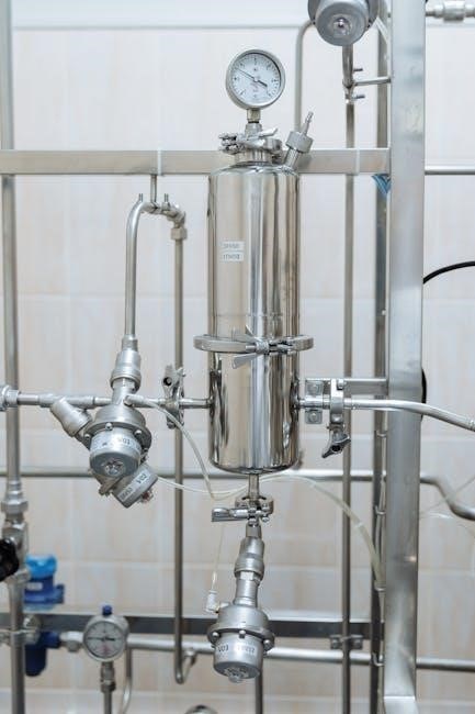
Pressure Regulator
A crucial component of Honeywell gas control valves is the pressure regulator. It ensures a consistent gas supply to the burner, irrespective of fluctuations in the incoming gas pressure. By maintaining a steady outlet pressure, the regulator optimizes combustion efficiency and prevents potential safety hazards. The pressure regulator is typically integrated within the gas control valve assembly, working in harmony with the automatic operators and other control elements. This component contributes to the overall reliability and performance of the heating system. Proper adjustment and maintenance of the pressure regulator are essential for safe and efficient operation, preventing issues like overfiring or flame instability.

Installation Procedures
Prior to installation, carefully review the manual. Check the power supply rating on the valve and make sure it matches the available supply, also install transformer, thermostat, and other controls as required.
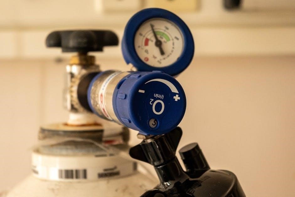
Power Supply Requirements
Ensuring the correct power supply is crucial for the safe and efficient operation of Honeywell gas control valves. Begin by checking the valve’s power supply rating, typically found on a label affixed to the valve body. This rating specifies the required voltage and frequency (e.g., 24VAC, 60Hz) for proper functioning.
It is imperative to match the valve’s requirements with the available power source to prevent damage or malfunction. Using an incorrect voltage can lead to overheating, component failure, or even hazardous situations. If the available power supply does not match the valve’s rating, a suitable transformer must be installed to step down or step up the voltage accordingly. Always consult the relevant electrical codes and regulations to ensure compliance and safety during installation.
Connecting to Pilot Burner
Properly connecting the gas control valve to the pilot burner is essential for safe and reliable ignition. Begin by carefully selecting the appropriate tubing, ensuring it is compatible with gas and meets all relevant safety standards. Connect one end of the tubing to the pilot outlet on the gas control valve, securing it tightly with the correct fittings.
Next, connect the other end of the tubing to the pilot burner, strictly following the pilot burner manufacturer’s instructions. Exercise extreme caution to avoid bending or kinking the tubing, particularly near the control valve, as this can restrict gas flow and impair ignition. Ensure a secure and leak-free connection at both ends. After connecting, perform a thorough leak test using a gas leak detector or soap solution to verify the integrity of the connection.
Transformer and Thermostat Installation
Proper installation of the transformer and thermostat is critical for the reliable operation of Honeywell gas control valves. Begin by selecting a transformer with the correct voltage and current rating to match the valve’s power requirements. Mount the transformer securely in a suitable location, ensuring it is protected from moisture and physical damage. Wire the transformer to the power supply according to local electrical codes, paying close attention to polarity and grounding.
Next, install the thermostat in a central location away from drafts or direct sunlight, ensuring it accurately reflects the ambient temperature. Connect the thermostat wires to the appropriate terminals on the gas control valve, following the wiring diagram provided in the manual. Double-check all connections to ensure they are secure and properly insulated. After installation, calibrate the thermostat and verify that it is communicating correctly with the gas control valve.
Operation and Control
Honeywell gas control valves offer precise operation and control through combined valve and ignition (CVI) systems and automatic valve functionalities, ensuring safe and efficient gas flow regulation.
Combined Valve and Ignition (CVI) Systems
Combined Valve and Ignition (CVI) systems, a feature of Honeywell gas control valves, integrate gas flow regulation with ignition control. These systems provide a safe and programmable ignition sequence. They also control flame monitoring and gas flow to the main or pilot burner. Honeywell’s CVI systems enhance safety and efficiency in gas-fired appliances. The VK4115V2012B model exemplifies this technology, managing gas flow and ignition seamlessly. These systems ensure reliable and secure operation by combining multiple functions into a single, integrated unit. This integration simplifies the overall system design and improves performance. Honeywell’s product manuals offer detailed guidance on CVI system operation.
Ignition Control Models (S4565, S4575, S4585)

Honeywell’s ignition control models S4565, S4575, and S4585 are designed for automatic ignition systems. These models work in conjunction with gas controls to provide reliable ignition sequencing. They are commonly used in various gas-fired appliances to ensure safe and efficient ignition. These controls offer advanced features for flame detection and safety shutoff. They enhance the overall performance and safety of gas-burning systems. Detailed information on these models can be found in Honeywell’s product manuals. These ignition controls are crucial for maintaining optimal system operation. Always refer to the specific manual for your model. This ensures proper installation and troubleshooting.
Automatic Valve Operation
Automatic valve operation in Honeywell gas control systems relies on solenoid and diaphragm-operated valves. The solenoid valve opens upon a thermostat call for heat, initiating the gas flow. Conversely, it closes when the call for heat ends, halting the gas supply. Subsequently, the diaphragm valve opens, allowing for further regulation of gas flow. This dual-valve system ensures precise control over the gas supply. This process is essential for maintaining consistent temperature and efficient operation. The interplay between these valves is carefully calibrated. This ensures optimal performance and safety. For detailed specifications, consult the Honeywell product manuals. This ensures proper system functionality and longevity.
Safety Features
Honeywell gas control valves incorporate crucial safety features. These include a resettable high-temperature cut-off and a Pilotstat safety mechanism. These features ensure safe gas control system operation, preventing hazards and ensuring user safety.
Resettable High-Temperature Cut-off
The Honeywell gas control valve features a resettable automatic high-temperature cut-off. This vital safety mechanism is designed to activate if the water temperature exceeds a safe limit. Once activated, the cut-off interrupts the gas supply, preventing overheating and potential hazards. This feature is crucial for maintaining safe operation and preventing damage to the system. To restore operation after a high-temperature cut-off, the system must be manually reset; This resettable function ensures that any underlying issues are addressed before normal operation resumes. Regular inspection and maintenance are recommended to ensure the high-temperature cut-off functions correctly and maintains optimal safety.
Pilotstat Safety Mechanism
The Pilotstat sub-assembly within Honeywell gas control systems incorporates a built-in safety mechanism. This mechanism ensures safe manual light-up and shutdown procedures. The Pilotstat’s primary function is to verify the presence of a pilot flame before allowing the main gas valve to open. If the pilot flame is absent or extinguished, the Pilotstat immediately shuts off the gas supply, preventing the accumulation of unburnt gas. This critical safety feature minimizes the risk of explosions and ensures safe operation. The Pilotstat also facilitates manual control over the gas supply, allowing users to safely initiate or terminate gas flow as needed. Regular inspection of the Pilotstat is essential.

Troubleshooting
When troubleshooting, consider the valve’s opening time specifications. A standard model opens in 26 seconds at 60 Hz or 32 seconds at 50 Hz. A fast-opening model is available, opening in 13 seconds at 60 Hz.
Opening Time Specifications
Understanding the opening time specifications of Honeywell gas control valves is crucial for proper system diagnosis. The standard model typically exhibits an opening time of approximately 26 seconds when operating at a frequency of 60 Hz, or around 32 seconds at 50 Hz. For applications demanding quicker response times, Honeywell offers a fast-opening model, characterized by an accelerated opening time of approximately 13 seconds at 60 Hz. These timings are critical for ensuring safe and efficient operation, particularly in systems requiring rapid gas flow. Deviations from these specifications may indicate underlying issues necessitating further inspection and potential maintenance or replacement of the valve.
Additional Resources
For deeper insights and specific model information, consult Honeywell product manuals. These resources provide detailed specifications, troubleshooting tips, and safety guidelines for your particular gas control valve.
Honeywell Product Manuals
Honeywell offers a range of product manuals that provide detailed information on their gas control valves. These manuals are essential resources for technicians and homeowners alike, offering comprehensive guidance on installation, operation, and maintenance. You’ll find specific details regarding your valve model, including wiring diagrams, troubleshooting steps, and safety precautions. These manuals often include exploded views of the valve components, aiding in understanding its internal workings. Always refer to the appropriate Honeywell product manual for your specific gas control valve to ensure safe and proper operation, as well as to avoid potential hazards. These manuals contain critical information.